BVDesigner152, its a good question that sadly may not have any particularly great solution... As Sage shows, you might want to consider these basic type configurations shown in my picture below instead, simply because they are so much less trouble and so much easier to work with. I think these 2 are the most common configurations among today's designers.
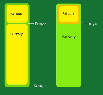
- SBexample1.jpg (20.33 KiB) Viewed 7718 times
There is also the type where fairway and green areas are completely separated from eachother by rough.
That being said, I dont think its fully impossible to have the configuration you're having, its just very tricky to get it to look nice, and odds are that if looking closely enough there will always remain at least a slight trace of weirdness. I did a very similar configuration to what you have (except that I used extrusion style seamblends, but I dont think that changes things too drastically) for my course (Amedal GK, its unlocked and can be viewed), and I think I got away with many T-style seamblends as you call them without them looking weird unless you actually make a project out of actively searching for them and unnaturally zooming in on them very closely. To explain better I marked sections of your own screenshot to make them easier to refer to:
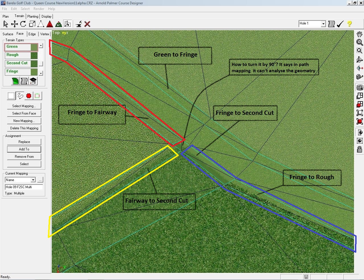
- SBexample2.jpg (695.53 KiB) Viewed 7718 times
The "solution" I came up with was to join 2 of the 3 blends together into a circle then fiddle enough with the 3rd one to make it join the other 2 as nice as possible. APCD seems to have a much easier time calculating path maps for closed circles rather than paths with 2 ends. In your case I think its safe to assume that if you keep going around with for example the sections I marked as blue and yellow, youll wrap around both the fairway and green into a big circle right? First I would calculate that as one path map. Then select the yellow section and make one Multi mapping for that one, and then select the blue section and make another Multi mapping for that one. Both those 2 Multi mappings will use the one same path mapping made for the big circle, you dont have to make a separate path mapping for each of them. (If both seamblends use the same set of planar mappings you dont even need to make 2 different multi mappings). If the circle still gets the error when trying to calculate the path, try remaking the path between the 2 sections you want to join together into a circle into a straighter one, and instead letting the red section have the sharp angle of the "T" shape. You could instead join red and blue sections into a circle, but because the fairway and fringe textures are visually closer to eachother than the rough texture, I recommend not doing it that way.
After that you fiddle about with the last remaining seamblend section of the 3 and try to make it look as good as possible... in my case my fringe and fairway textures were VERY similar in visual look so it wasnt too hard, but one method I did was to add verts closer to the T intersection along the fairway-fringe (red) border and leave a tiny piece that touches up against the (blue+yellow) without blending. After blending I moved verts around a little to achieve the best look. It may not be a good solution unless 2 of the 3 textures are visually similar enough... Im not sure.
In places where possible, a simpler method is hiding such T intections with a tree, bush, 2d grasses or some other object so it cant be seen anyway. Obviously that wont work for fairway/fringe/green areas...
If you want you can check out the thread where I asked basically the same question as you at
viewtopic.php?f=7&t=231 Within it is some good info about how to get path maps to calculate for example.

